RC Aircraft
Cheetah RC Conversion

Conversion Steps
Decided to try using pitcherons instead of elevators and ailerons. From the videos I watched, it allowed the glider to do tight rolls. I used this video as the main reference. This video was helpful when figuring out the tranmitter mix for the pitcherons, and this video was as well when it came to the idea of using a quadcopter ESC and a mini DC-DC voltage buck converter for the BEC.
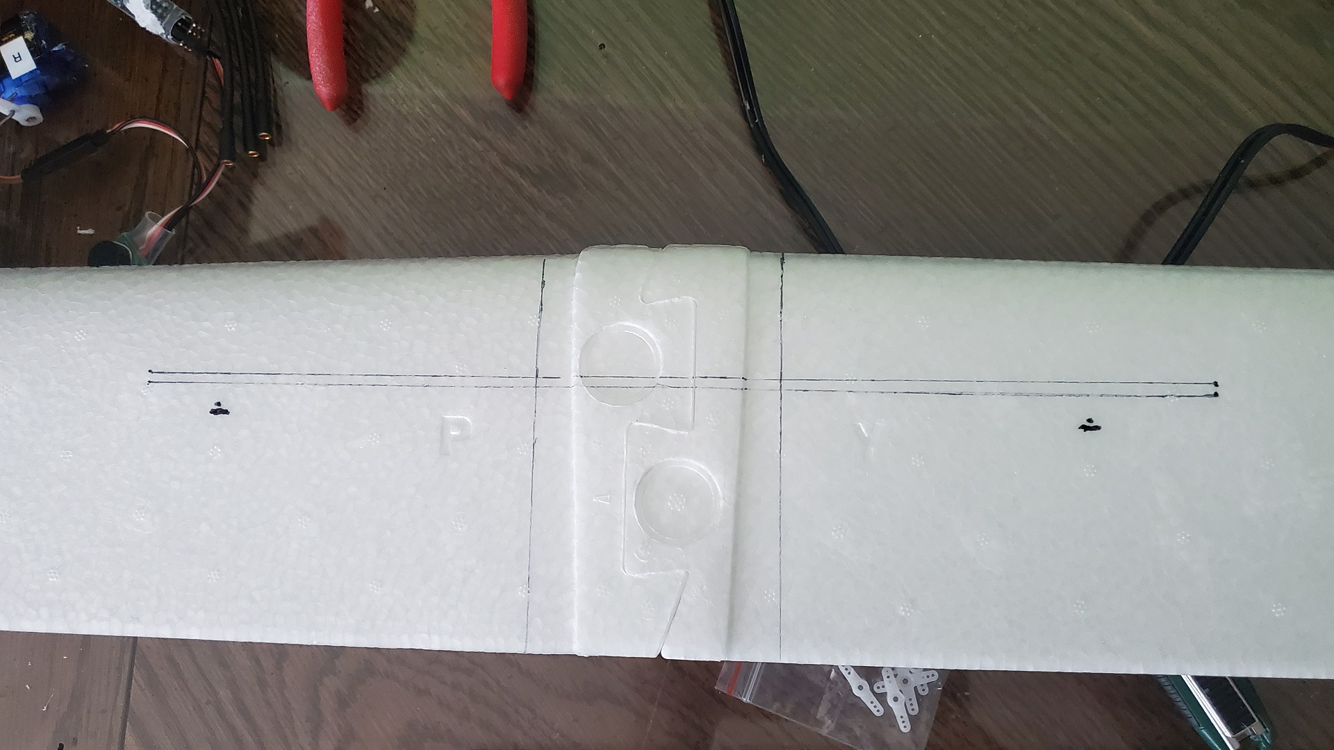
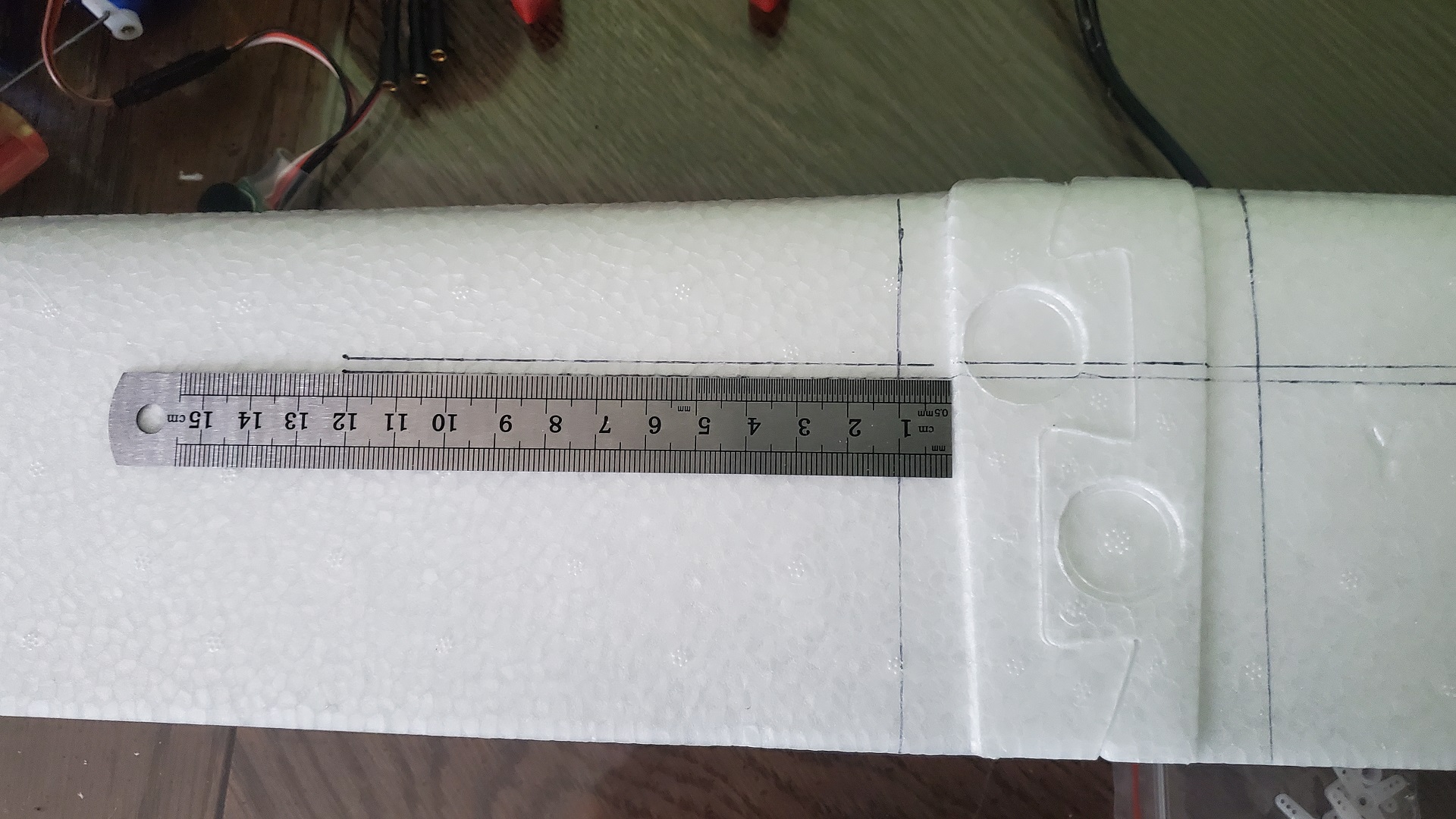
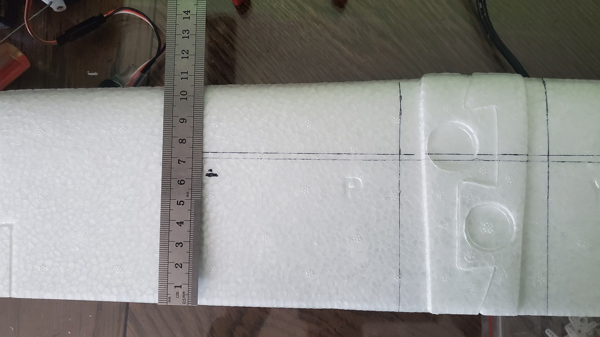
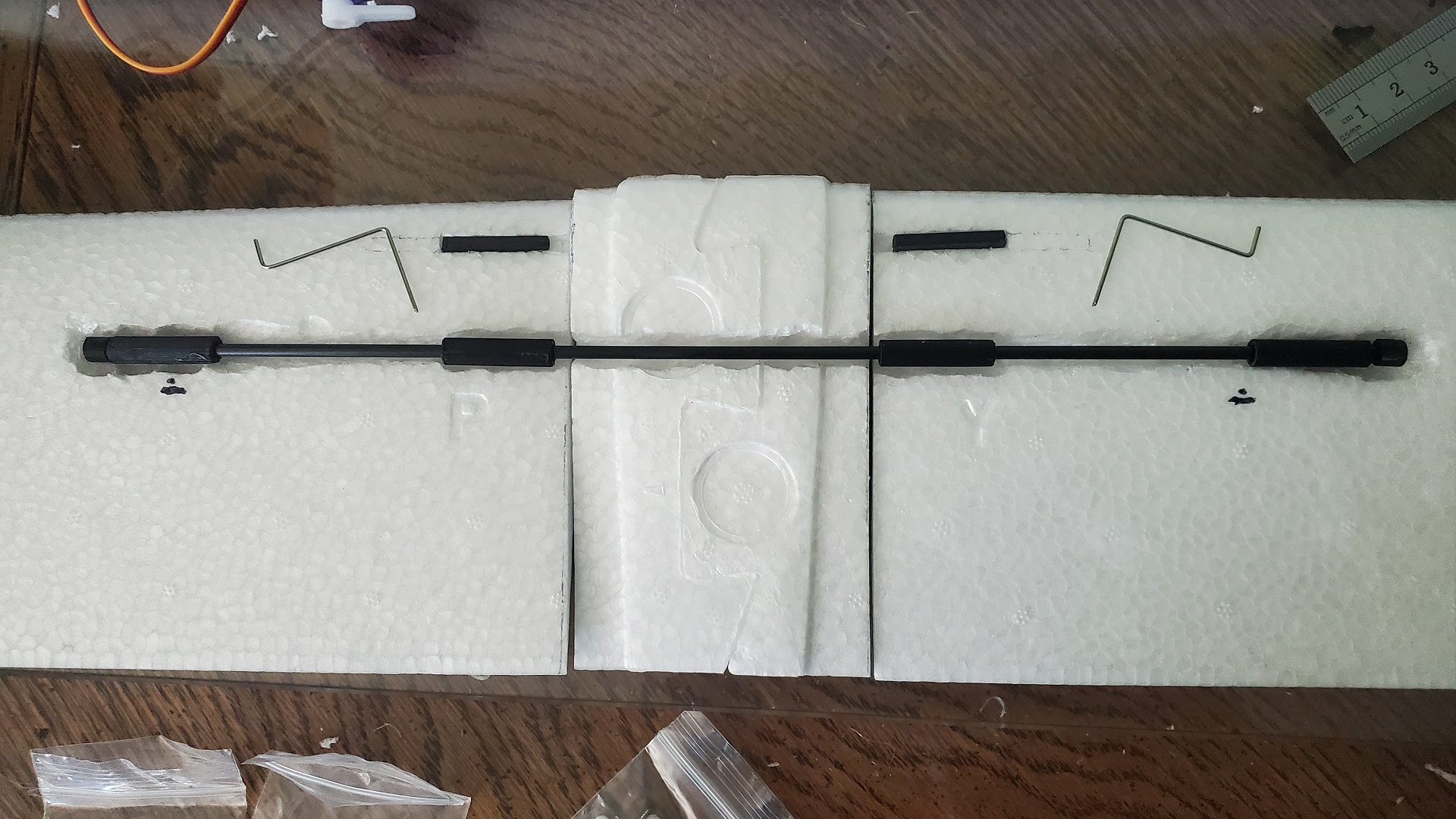
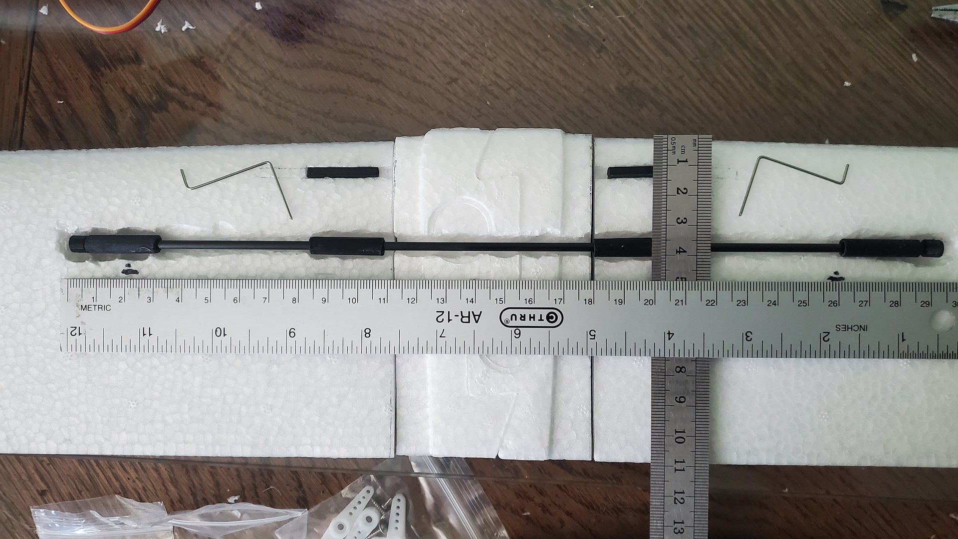
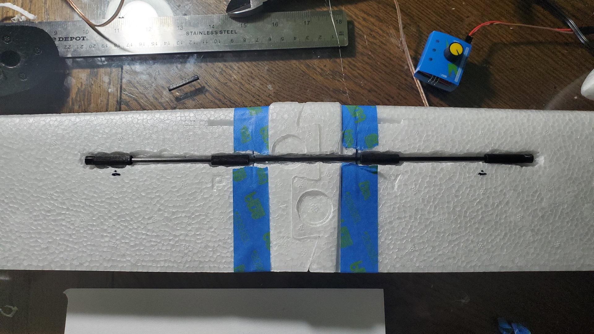
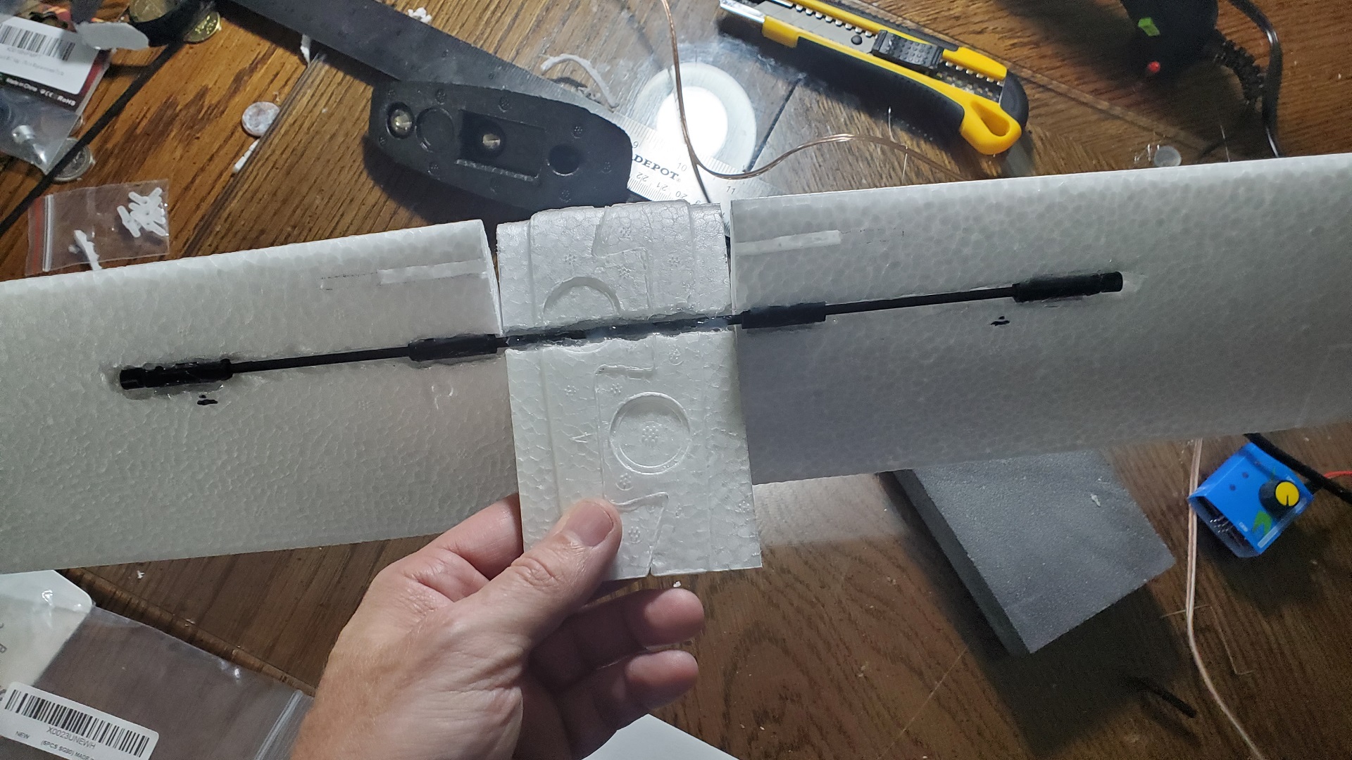
First step was to figure out how to do the wingerons. I marked the CG points under the wing with the glider all put together before doing anything else. I used a 3mm carbon rod instead of the 4mm one mentioned in the reference video. I created some half-tubes in Blender that I could just glue together, and then hot glue in place on the wings, which I figured was much easier than sourcing the right size carbon fiber tube, and also created and printed some endcaps. After gluing the two-halves of the four small tubes together, I put them on the carbon fiber rod and glued on the endcaps. I created a channel on the wings for the rod, and taped the wings together so they wouldn't move when gluing down the four tubes into the wings, as well as the carbon rod itself to the middle section.
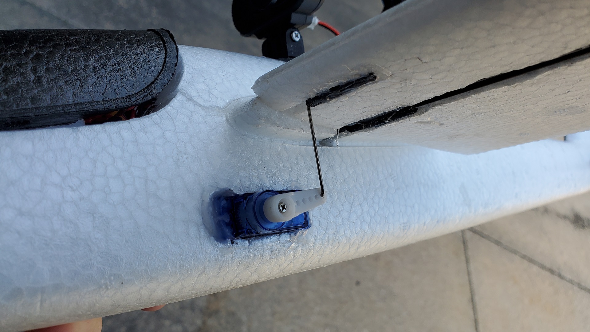
Created and printed out some small square tubes that would hold the 1mm wire control linkages on the wings in place when installed on the servos. These were glued in after cutting out channels for them on the underside and inside front of both wings. This was easier than drilling into the wings as shown in the reference videos. Made some z-shaped control rods that would first slide into the square tubes on the wings, and then could be slightly bent outwards to place the other end of the wire in the servo control horn hole to spring back and lock into place.
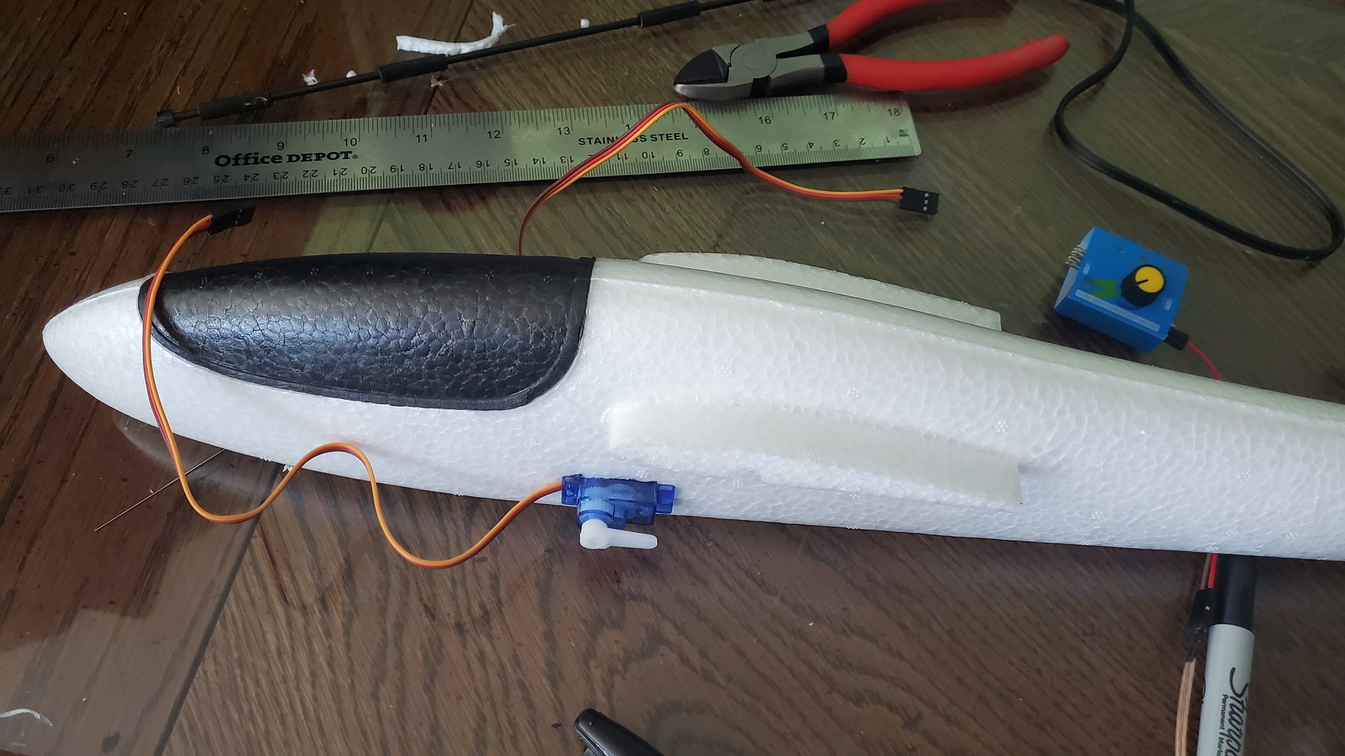
I used a coat-hanger thick wire heated with a propane torch to melt channels from the fuselage to the motor, as well as from the fuselage to the servo cutouts for all the wiring. The completed wings with the glued rods was placed into the fuselage. The control rods were connected from the wings to the servos.
For pitcherons, pulling down on the right stick should result in the leading edge of both wings going up, trailing edge going down. Pushing up on the right stick does the opposite, leading edge of both wings should go down. When pushing the right stick to the right, the leading edge of the right wing should go down, and the leading edge of the left wing should go up. Pushing the stick left should do the opposite. View the reference video for details.
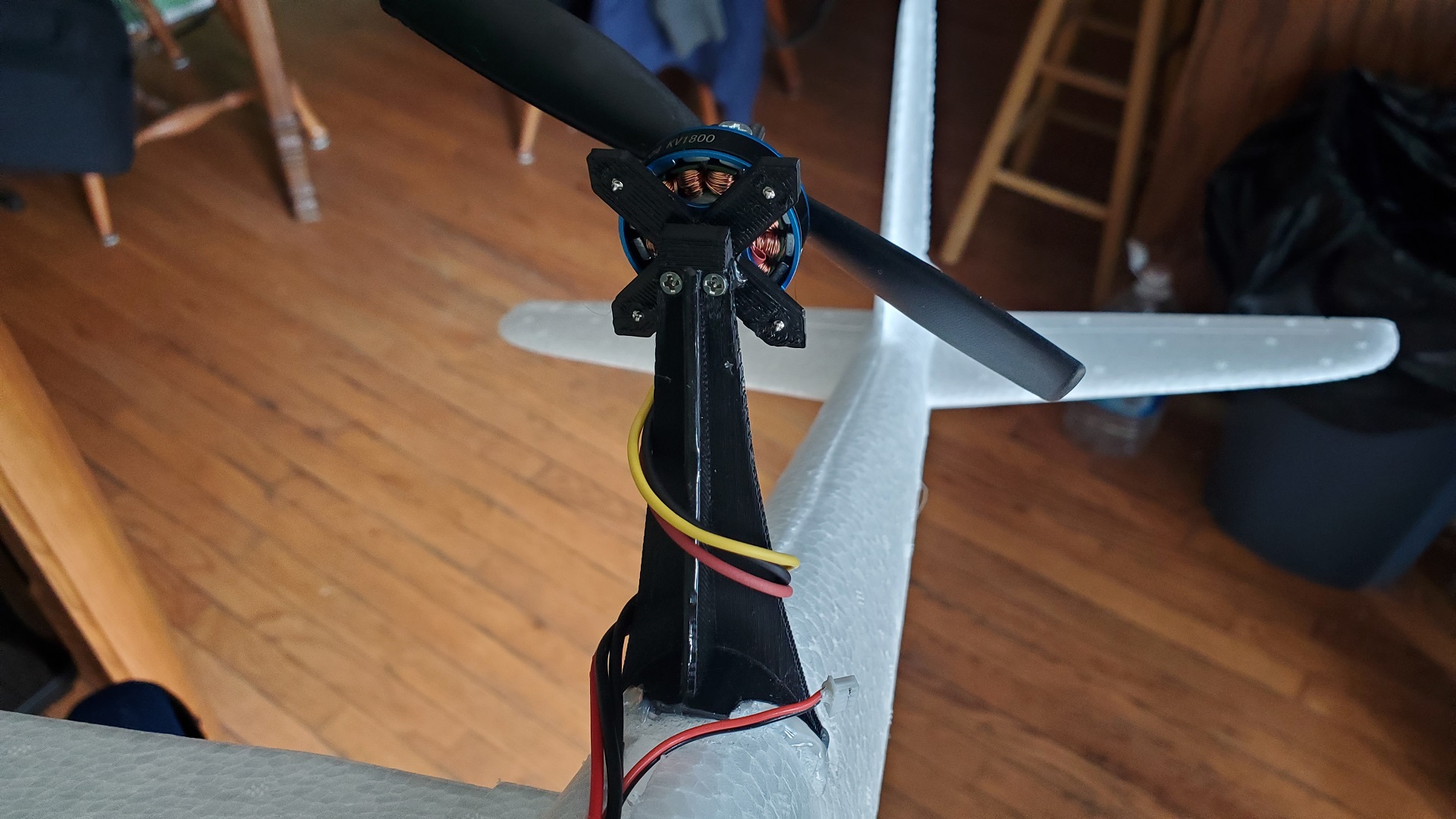
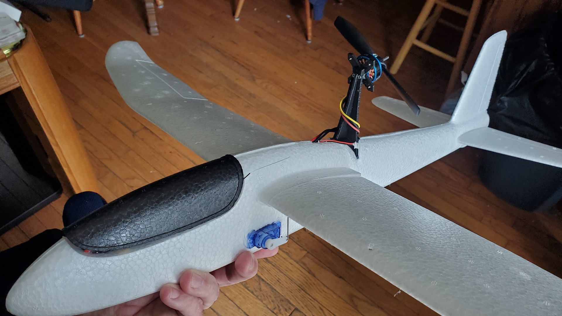
I didn't like the old-wooden-stick-found-in-the-woods as a motor mount as was used in the reference video, so I decided to create one myself in Blender to 3D print.
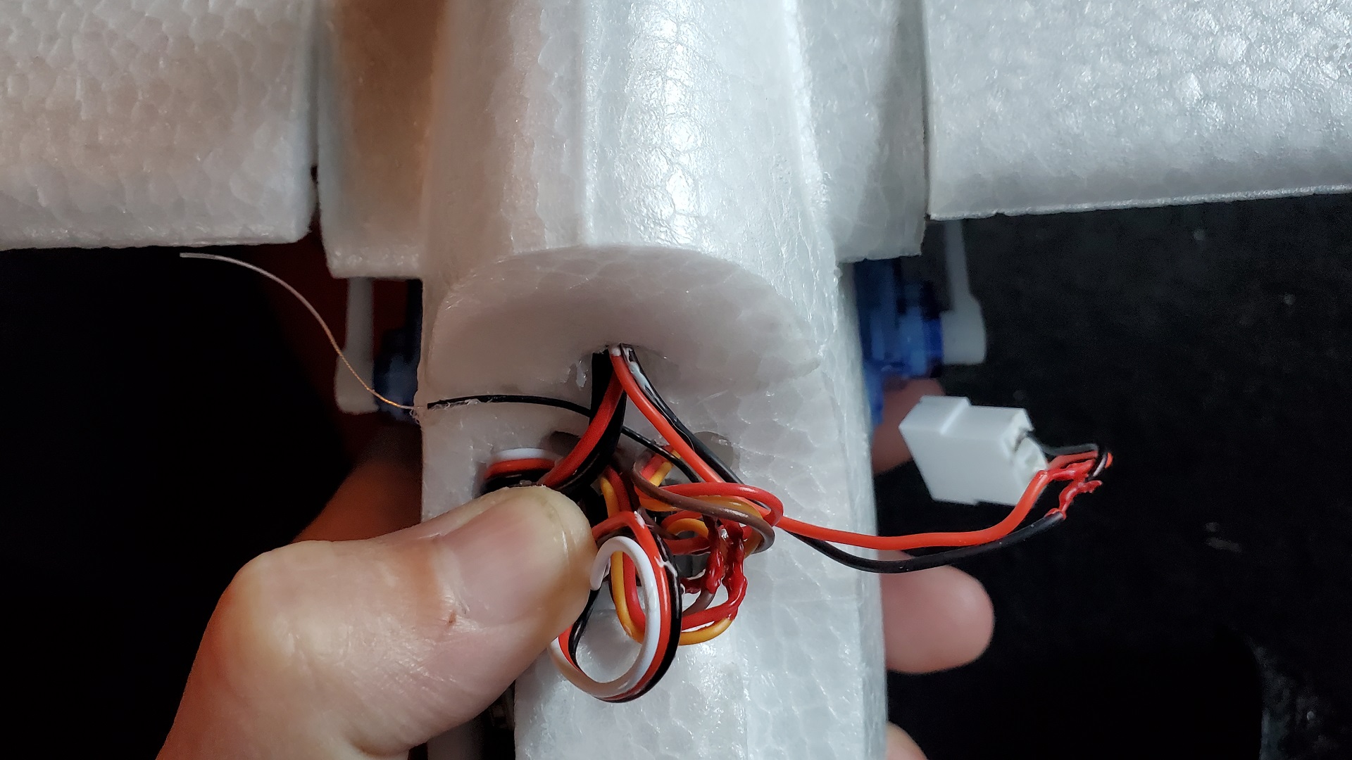
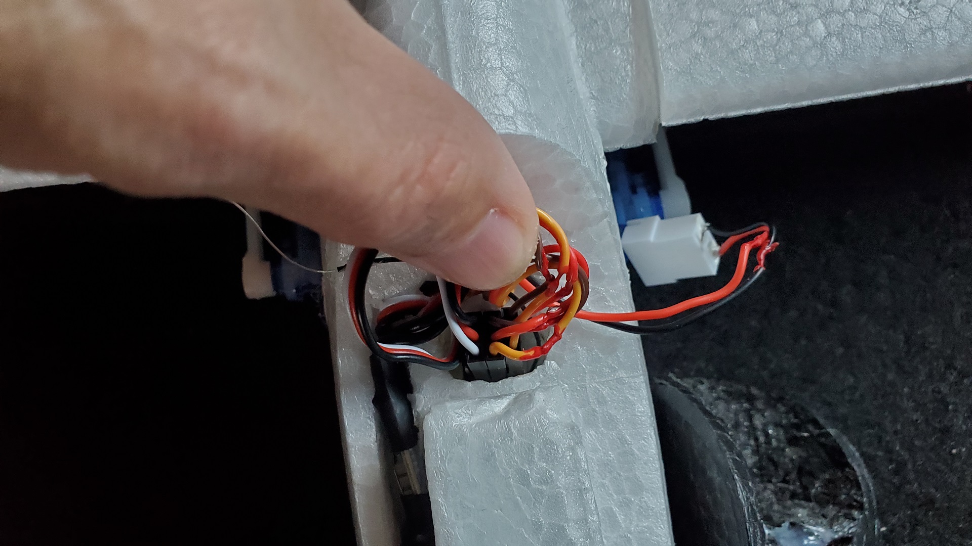
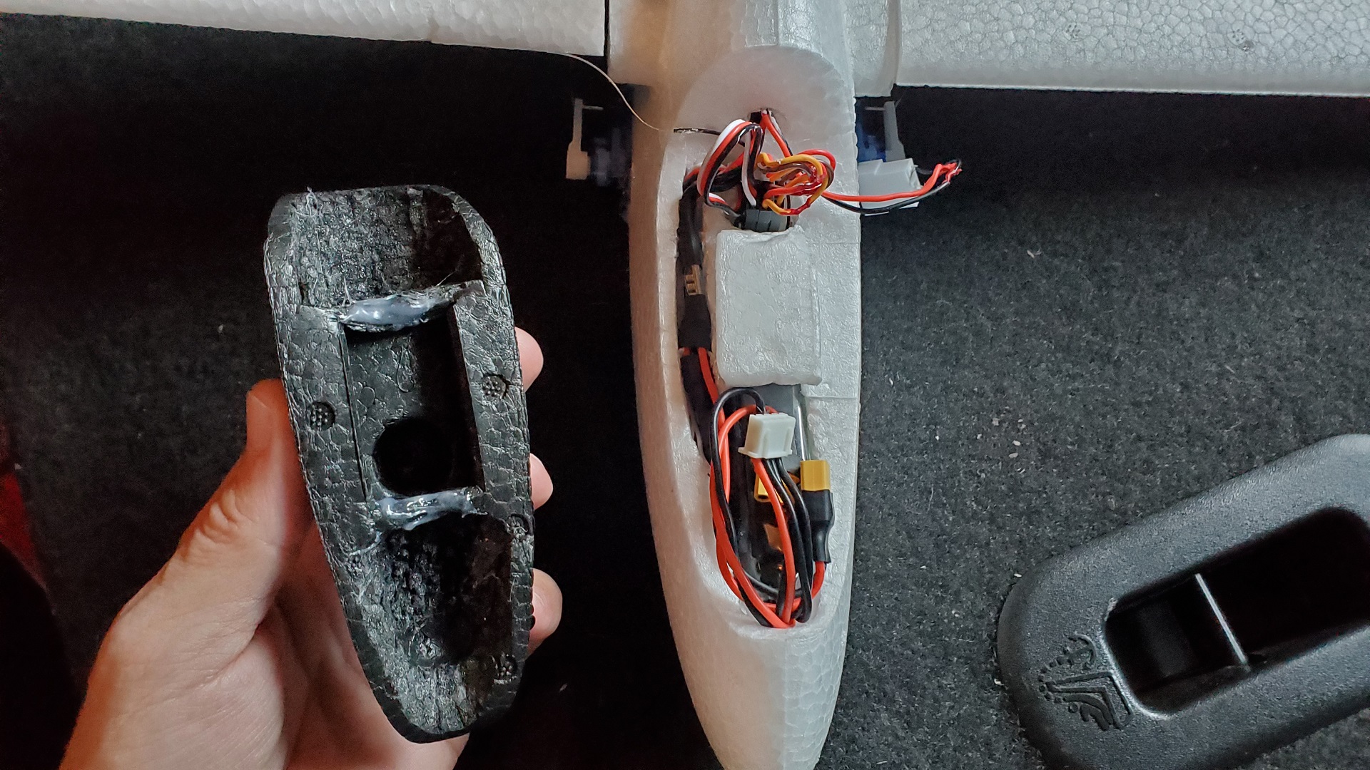
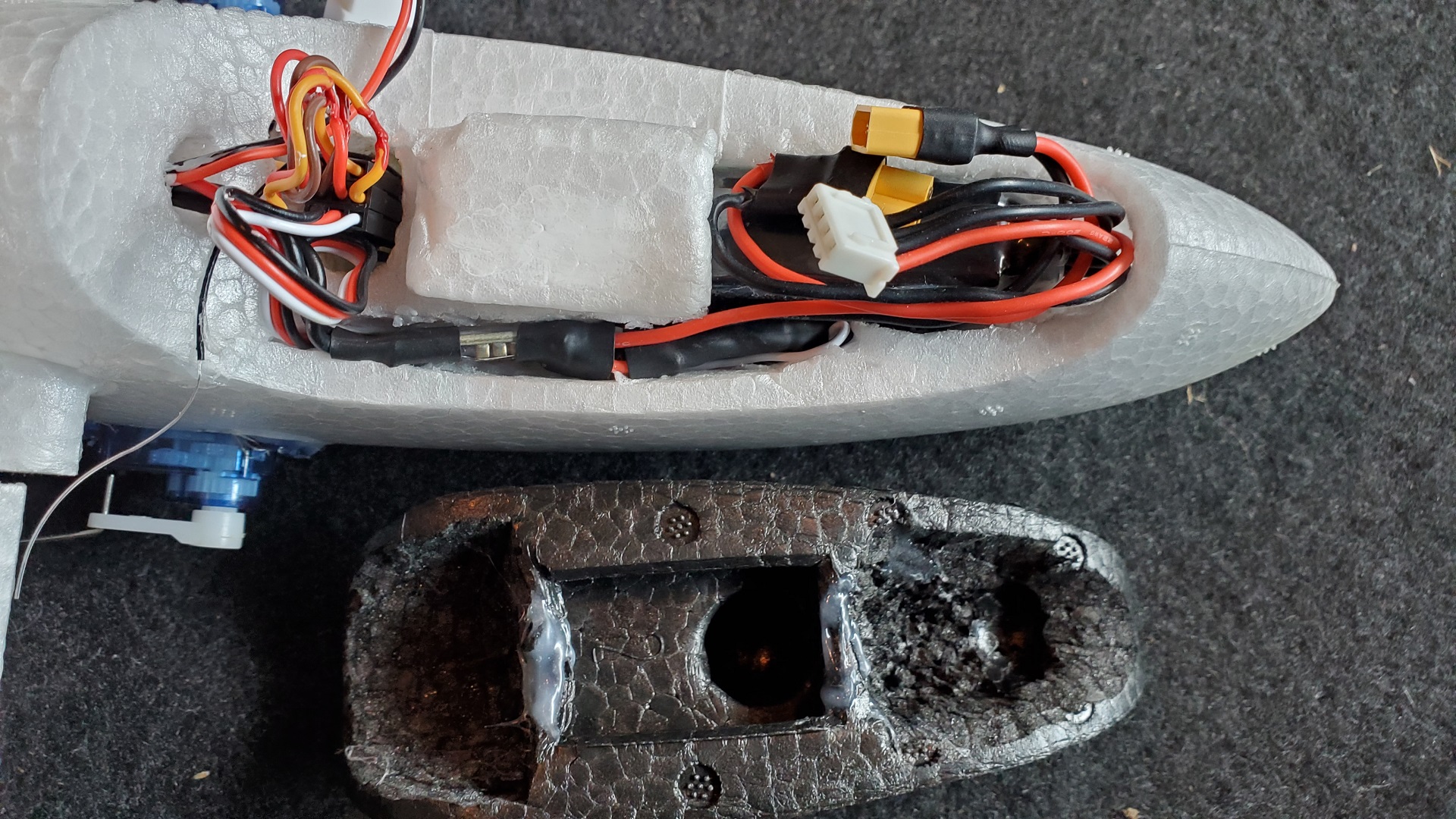
Cut some space on the left of the cockpit for the ESC, and in the back and straight down for the receiver. Then cut space at the front for the battery and down under the rectangular foam piece that holds the canopy, making sure to keep the CG in balance. The two ball bearings were removed from the canopy, and parts of foam at the front and back were also cut out to allow room for the wires and connectors.
The original 12 amp ESC that came bundled with the motor was basically useless. The motor would stutter quite badly at low throttle, even after calibration. Some forum threads stated this was normal, however, this is the first time I've encountered such an issue. The bigger problem was that after a few minutes of flying, the motor would just shut off, and it seemed be after trying a higher throttle maneuver. I tried another 10 amp one, and the issue was the same, motor would stutter at low throttle and die after high throttle from the ESC resetting. Not quite sure why considering the reference video showed he was using only an 8 amp ESC. It could also just be a problem with my particular motor, it could be slightly defective and drawing too many amps. My guess was that it needed at least a 20 amp ESC so to save space instead of using the standard bulky RC plane type, I used a 20 amp ESC for quads as well as with a mini DC voltage buck converter, as was shown in this video. I put an extra 20v 220uf capacitor across the power input leads just to be safe, even though there's a SMD one on the ESC board.
Flights
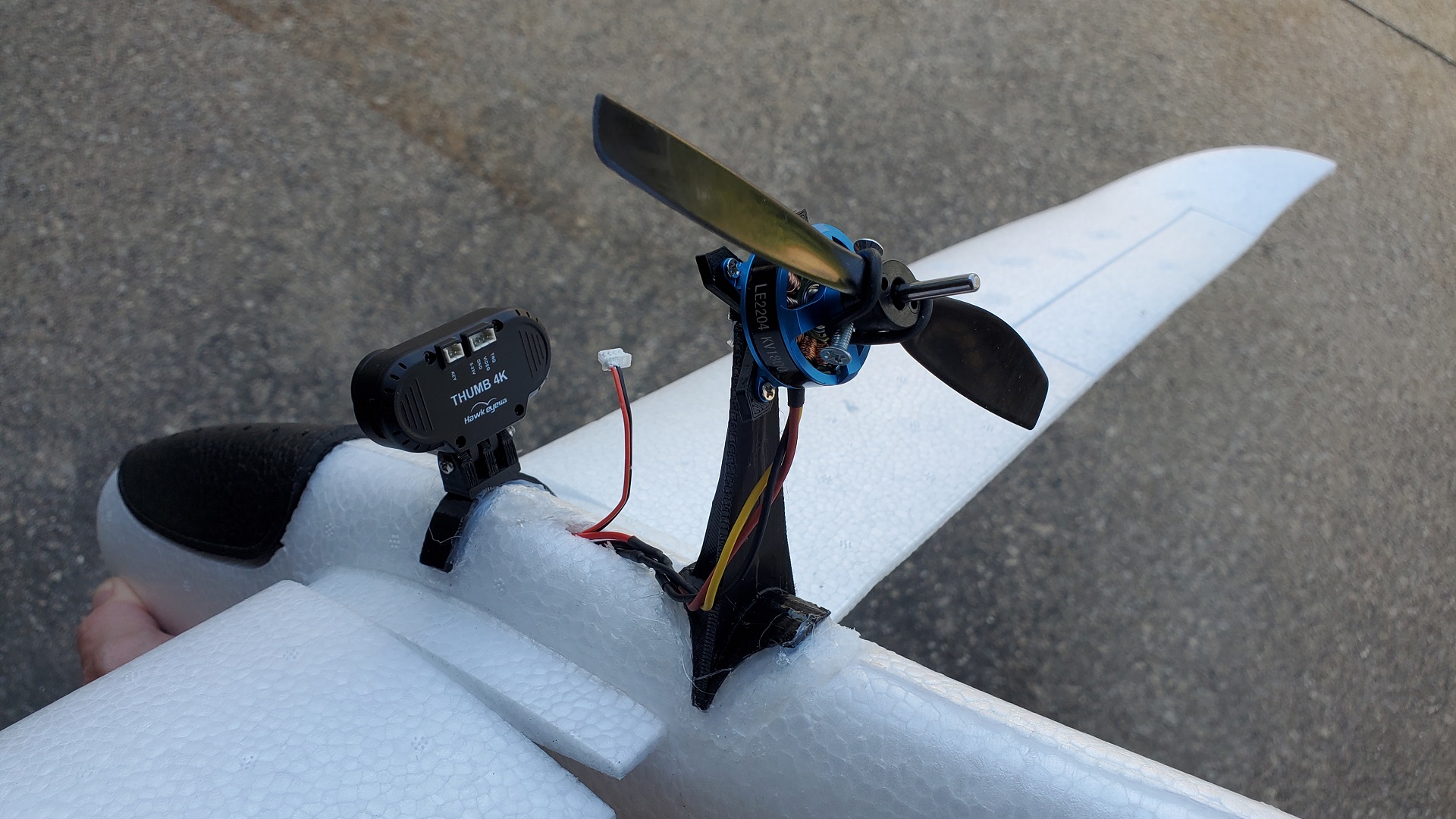
 After getting the mix into a better state (about 60% for ailerons compared to elevator), I created a mount for the Hawkeye thumb camera, and ran another wire through the fuselage to connect it to the battery charge lead.
Cheetah v2
Unfortunately, even though I could fly this, it wasn't terribly stable. Everytime I flew it, it was a gamble whether it was going to crash or not. I felt like I had 65% control over this thing - not exactly great. It really bothered me that it would stall so easily; if the speed was even just slightly too low, this thing would flip and dive into the ground. It's supposed to be a glider, not a jet, so I couldn't understand why it was requiring so much speed to stay in the air. At first I chalked it up to maybe that's just how pitcheron planes work, but it felt like more than that after I watched other videos of the same type of planes apparently without the same issue.
Another issue was that the motor was cutting out intermittently, and I wasn't sure why. I would throttle up, and the motor would just die, and I'd have to cut the throttle and then it would come back, but it would just keep happening. And since it was a glider that didn't like to glide and needed so much speed, this was causing more crashes. I replaced the motor, ESC, and receiver, and none of those fixed the issue. It was perplexing, because it worked previously just fine. However, I did crash it a few times, and I did have to resolder the motor wires, since the prop would sometimes slice into the wires. I figured maybe one of the motor wires were broken but not visible because the prop hit the wire, maybe breaking or weakening it but not the insulation, so I wasn't able to see exactly where the problem was.
 The tipping point came with this flight. Usually when you fly a plane, you get used to it and it gets better and better. This was the opposite. On this flight, right off the bat, it just was terribly unstable. I tried correcting it to bring it back towards me, but would go upside down, so I'd correct, but I couldn't get it turned around. It started going towards the roof, I pulled away, but not in time for it to go right into a tree with the most gnarly, ensnarling branches I'd ever seen on a tree. One of the wings came off and was stuck where the initial crash was. At first I was trying the motor, but the mount already came loose, so wasn't much help. Luckily I had control over one wing, and it being a pitcheron saved me in this case, I was able to wiggle it back and forth until it finally came loose. The wing was way too high for a ladder to get to. There was a playground ball laying there I tried to use, but it was just up slightly higher than I could possibly throw the ball. I had to come back later with a BB gun and shoot it out of the tree.
I figured I had the center of gravity a bit off, so I moved the motor forward, thinking it was tail-heavy, which was causing the stalling. This was a mistake, and it crashed, since with it being too nose-heavy, it would dive towards the ground on take-off and I couldn't pull out to stop from crashing. I kept playing with moving the motor around, crash after crash, and I was really getting frustrated as to why this was giving me such trouble. Then when I was holding it by the fuselage with a finger on both sides I made a startling discovery: it wasn't the CG being too far forward or back - it was the CG being too high. It was naturally turning over and going belly up because the motor was too heavy. I really didn't know what motor to put on it, and just used some cheap ones that I thought were lower-powered so figured they would work. However, for a foam glider, a 2204 motor was overkill. This would also explain the motor issues - I may have been pulling more amps than the battery could handle putting out. It may have worked initially since the battery was new, but after a while it just couldn't keep up.
With this in mind, I looked at my other planes and decided the 1306 motor I was using on the Mini Chiroptera should be sufficient. I modified my custom motor mount in blender to both accomodate the new motor as well as made it as short as possible without the smaller three-inch three-blade prop hitting the fuselage. Now my issue was that I had lost quite a bit of motor weight, so it meant I'd have to move it back to keep it balanced. I moved it as far back as I could, as well as made the thrust angle more shallow. It was still nose-heavy. I replaced the current 500 mah batter for another, except it was a HV battery, which was a bit lighter. This helped, but not enough. I hot glued a few folds of lead ribbon to the bottom of the tail, and that worked fine.


My first flight, it went almost straight up, then right back down. Not good. However, with all the adjustments I was trying previously, I figured it was just the elevators being way out of trim, so pushed them foward as far as I could trim them. Tried it again, and I was amazed. It flew - like an actual glider should. Easy to control, no having to fight to keep it in the air. It was perfect. I had been fighting with this thing for so long now, crashed it about a dozen times in a row, and was about ready to just give up. If this hadn't have worked, I would have scrapped this idea and tried putting the motor in the front instead. I was hoping it have to figure something out, no how matter how long it takes me, or if it kills me, because I steadfastly refuse to let anything "beat me".
 Here's the next flight, unfortunately there was a bit of wind coming from the right, and instead of getting better, it got quite a bit worse, to the point where I didn't want to press my luck any longer and brought it in for a landing. And it was the slowest, easiest, shortest landing I've ever had with this plane.
Parts List
- Cheetah Foam Hand Glider
- 1306 Motor - 3100 Kv
- ESC 20 amp (for drone)
- BEC Mini DC-DC Buck Converter
- 500 mah 3s Lipo Battery
- FS2A Mini Receiver
- 3050 3 inch 3 blade Propeller for 5mm shaft
- 3mm carbon rod, 29cm length
- 9g Servos x2
Cheetah STL Files - Top part of motor mount can be attached with two M2x5 screws, as well as the motor itself with four M2x5 screws. If you're worried about crashing, consider hot gluing the top part of the mount to the base instead of using screws, that way if you do crash in a bad way, it will likely separate at the glued part instead of cracking the plastic.