CentPIed: Centipede Arcade Restoration and Raspberry Pi Conversion
Video Conversion
Enter the Raspberry Pi - an extremely small board that can run Linux, do emulation, and output video to HDMI and RCA. I was hoping that others had done some work trying to get these to work with the old arcade monitors using display ports or GPIO pins on the R-Pi with special drivers or whatnot. However, it seems such a thing isn't possible (currently). One day though, I came across an article describing how an arcade was doing exactly what I wanted. They described how to use the HDMI output to an active HDMI to VGA converter and then to a VGA to RGB converter. Perfect! Here a link to the original article.
So, the big part is the GBS 8100 VGA to RGB converter. You can get these for as little as $25 on ebay. Here is the "manual" for it - obviously a bit lacking. The ACTIVE HDMI to VGA adapter you can get for like $15 on eBay, Amazon, etc. Stressing ACTIVE here - not passive. You'll require a female to female VGA cable to connect these two together. You'll also need a 1-2 amp 5v power supply for the GBS-8100 board if you're not going to use the 5v from the arcade cabinet's power supply. You'd only want it separate if say you adjusted the GBS-8100's graphics settings and didn't want them reset every time you turned off the machine - unfortunately the settings won't stick once it's powered off.
As you can see from the manual, not the best help when it comes to how to wire this to the arcade monitor. It shows the RGB pinout as 'R', 'G', 'B'...some Chinese character, and 'S'. My best guess is that the 'S' is Composite Sync. Was it negative or positve though? Venturing another guess that the unknown symbol is Ground. Now how is this going to wire up to the existing pin out connections of the harness?
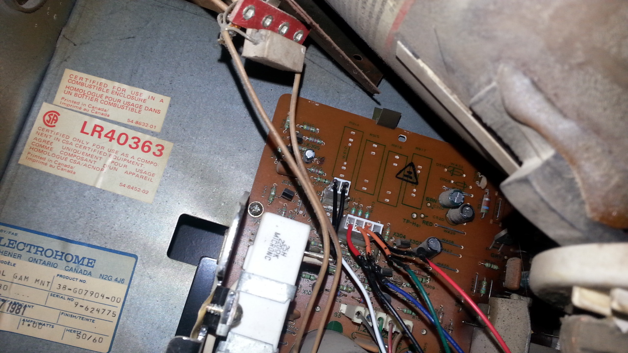
I found the answer to the monitor connections by looking at the label, and it's an ElectroHome G07. The label and printing makes it look like maybe this thing was hot off the press - in 1962. This site had the information I needed. It showed how to hook up the syncs, and how to hook them up if you had either negative or positive separate or composite syncs. So all bases covered there. Just had to figure out which one it was - I still didn't know if the GBS-8100 was outputing a positive or negative sync - or a sync at all for that matter from that mysteriously named pin.
I figured I'd just test it out by making a small interface cable, one end from the one that came with the board, the other from an old PC connector. It was just about the right size so it would fit the pins on the monitor board ok. It was 6 pin, but I cut it so it was actually now a 2-pin one and a 4-pin one. This way, I could try the 2-pin one on both the positive and the negative sync input pins of the monitor board to see which one worked.
So I fired it up and tried it out. Got a horrible rolling picture, when connecting to both the negative and postive syncs of the monitor, so I wasn't sure what was wrong. I then tried adjusting the monitor adjustment pots on the board, and after some trial and error, finally got a stable picture. This ability to get a three and a half decade old arcade monitor to work on current technology hardware was really a huge success and motivator to finish the project all the way through.
LINK TO VIDEO
The pinouts for the manual of the Centipede board show the Red, Green, Blue, as well as Horizontal and Vertical syncs. An undocumented one is pin 12 of P19, which is Composite Sync. Ideally after testing, I would have made another, smaller interface board just like I did for the main interface board and use that, which would also use the audio connections. However, the board is outputing a positive sync signal, and the GBS-8100 appears to output a negative one, so the existing sync connection of the harness won't help as they go to the positive sync inputs of the monitor, not the negative ones. This means it does indeed have to be connected directly to the monitor board. Just makes a bit more work if one were to reconnect an original board (but in my case, don't see that ever happening anyhow).
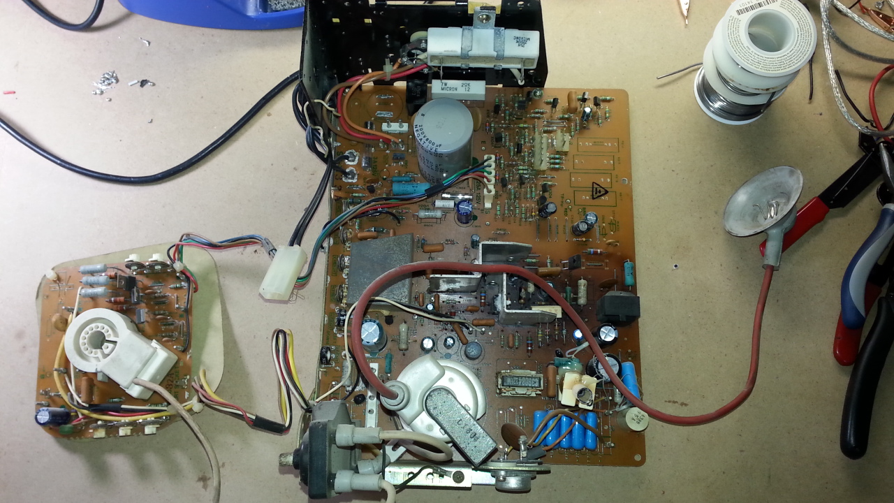
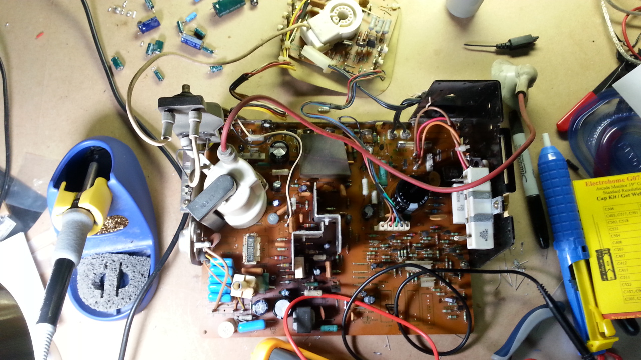
After some boot-ups, however, I noticed that the picture would still hang up and roll, and some of the pots I had to crank all the way to the end of their range. I figured there was probably a capacitor replacement that could be done, and I found plenty online after a search on eBay. The one I got had 18 capacitors to replace, was around $12, look up "G07 cap kit". I also bought a replacement for the large capacitor on the board, which was another $10, look up "G07 filter cap". I figured it best to just replace them all at once. Thankfully removing the board was quite easy, as I didn't have to remove the whole monitor or anything crazy to do it. This excellent video shows how. With all I needed, I set out to do the capacitor replacement. If you have a good soldering station and a solder sucker, this shouldn't be any problem. Here's my experience and some tips. (TODO: add video)


